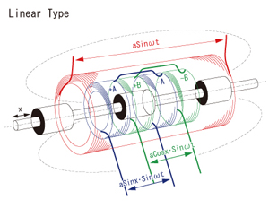
About Magnetic Induction SensorsMagnetic Induction Sensors of MURATEC by magnetic induction and phase detection method invented by original originality Magnetic Induction Sensors Sensor Operating PrinciplesMagnetic Induction Sensors of MURATEC is composed of the magnetic substance that moves in the conversion circuit, the first winding coil, the second winding coil, and the coil.
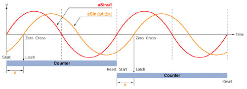 FeaturesThe miniaturization is achieved with the sensor of an absolute output. The Magnetic Induction Sensors achieved the miniaturization with absolute detection by adopting a sensor structure of a simple magnetic induction method and an original detecting scheme. Moreover, it corresponds to the length scale detection by counting the pitch of absolute. Excellent repetition character Magnetic Induction Sensors detects displacement and the position by converting mechanical displacement into the phase lag (time) between signals, and measuring for that time. As a result, an excellent repetition character is achieved. High accuracy and high resolution Magnetic Induction Sensors obtains a high resolution by matching the size of the mechanical displacement of the primary detecting element to two two phaseshift amount radians of the conversion part, and dividing 16 bits of the amount in the phaseshift (It is equal to division into 65536). The temperature drift is controlled at least Magnetic Induction Sensors is composed of an electromagnetic coil. The amount of the temperature drift is operated, canceled in the converter, and Magnetic Induction Sensors can be suppressed to the minimum though the temperature drift originates in the resistance change according to the temperature of the winding. It is strong under a bad environment. The primary detecting element of Magnetic Induction Sensors is strong in the vibration and the impact because it is composed only of an electromagnetic coil, and excellent also in the resistance to environments to oil, dust, and the temperature. Etc, It is also possible to set up the conversion part in influence by the environment a little, remote space. Maintenance free Magnetic Induction Sensors is maintenance free because of the complete contactless detection. The performance is demonstrated enough under all the environments by the achievement of the structure that the influence of dirt is not received easily. |